ISO 16750-4 Climatic Test Chamber Test Method
ISO 16750 certification is designed to qualify road vehicles. This document specifies environmental procedures and tests for electrical and electronic equipment. In fact, it applies to the electrical and electronic systems/components of the vehicle.
It describes potential environmental limitations and specifies recommended tests and requirements for specific mounting locations on/inside the vehicle
Test method
Perform the test in accordance with IEC 60068-2-1, Test A, at a temperature of-40 C for a duration of 24 h unless otherwise specified in the DUT specification. The operating mode of the DUT is 1.1, as defined in ISO 16750-1
Test method
Perform the test in accordance with IEC 60068-2-2, Test B, at a temperature of 85 C for a duration of 48 h unless otherwise specified in the DUT specification. The operating mode of the DUT is 1.1, as defined in ISO 16750-1.
Test method
Install the DUT in a temperature chamber, decrease the temperature in steps of 5 °C from 20 C to Tmin, andthen increase the temperature in steps of 5 C from Tmin to Tmax (see Table 1). Wait at each step until the DUT has reached the new temperature. Perform functional tests operating mode 3.2 in accordance with ISO 16750-1 at minimum supply voltage, Usmin and at maximum supply voltage, Usmax in accordance with the specified ISO 16750-2 code letter, at each new temperature step. Switch the DUT off during transition tothe next temperature.
Perform the temperature cycling in accordance with IEC 60068-2-14, Test Nb.
Operate the DUT electrically (functional test) after the whole device has reached Tmin for the shortest possiblel duration in order to check the correct function of the device. In addition, operate it electrically between 210 min and 410 min of the cycle (see Figure 2). Use operating mode 3.2, as defined in ISO 16750-1, for the phasesl with electrical operation. The changes in temperature shall correspond to the specifications given in Table 2. For tests including hotsoak temperature, TmaxHS, see Table 3. Figure 3 illustrates the temperature cycle with hot-soak phase, using code F as specified in Table 1. The long period of electrical operation is started at 20 °C in order to allow possible condensation of humidity on the DUT. A permanent operation starting at Tmin would prevent this due to the electrical power dissipation. Additional drying of the test chamber air is not permitted. Perform 30 test cycles as specified.
Test method
Perform the test in accordance with IEC 60068-2-52, Test Kb. Select a severity from Table 4 and Annex A. Use operating mode 1.2, as defined in ISO 16750-1.Carry out a visual examination with the naked eye, at normal strength of vision, with normal colour perception, at the most favourable distance and with suitable illumination.
Test 1: Damp heat cyclic test
Perform the test as specified in IEC 60068-2-30, Test Db, Variant 1:upper temperature: +55 °C;number of cycles: 6. Perform a functional test (operating mode 3.2 in accordance with ISO 16750-1) when the maximum cycle temperature is reached.
Test 2: Composite temperature/humidity cyclic test
Perform the test as specified in IEC 60068-2-38, Test Z/AD.Perform a functional test (operating mode 3.2 in accordance with ISO 16750-1) when the maximum cycle temperature is reached.
Test 3: Dewing test
Perform the test with reference to IEC 60068-2-30, Test Db, using the variant illustrated in Figure 8:upper temperature: +80 °C;number of cycles: 5. Use operating mode 2.1 in accordance with ISO 16750-1 during the complete test sequence. The temperature and humidity profile has been defined to generate a dewing effect similar to that in thel vehicle environment.
As an ISO-17025-certified climatic test chamber expert, JOEO recognizes the importance of climate load compliance testing, meeting environmental test requirements can be difficult, and JOEO engineers take a consultative approach throughout the test program, allowing us to deliver accurate test reports quickly, Contact us for more information on ISO 16750-4 climate stress environmental testing.
It describes potential environmental limitations and specifies recommended tests and requirements for specific mounting locations on/inside the vehicle
ISO 16750 climatic test chamber test method
Low-temperature tests
This test simulates subjects being exposed to low temperatures without electrical operation, such as during transportation of systems/components. The failure mode is insufficient frost resistance, such as LCD freezing.Test method
Perform the test in accordance with IEC 60068-2-1, Test A, at a temperature of-40 C for a duration of 24 h unless otherwise specified in the DUT specification. The operating mode of the DUT is 1.1, as defined in ISO 16750-1
High-temperature tests
This test simulates subjects being exposed to high temperatures without electrical operation, such as during transportation of systems/components. The failure mode is insufficient heat resistance, such as warping of the plastic housing.Test method
Perform the test in accordance with IEC 60068-2-2, Test B, at a temperature of 85 C for a duration of 48 h unless otherwise specified in the DUT specification. The operating mode of the DUT is 1.1, as defined in ISO 16750-1.
Temperature step test
This test checks whether mechanical and electrical equipment fails within a small part of the operating temperature range.Test method
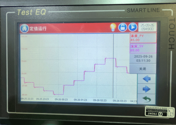
Install the DUT in a temperature chamber, decrease the temperature in steps of 5 °C from 20 C to Tmin, andthen increase the temperature in steps of 5 C from Tmin to Tmax (see Table 1). Wait at each step until the DUT has reached the new temperature. Perform functional tests operating mode 3.2 in accordance with ISO 16750-1 at minimum supply voltage, Usmin and at maximum supply voltage, Usmax in accordance with the specified ISO 16750-2 code letter, at each new temperature step. Switch the DUT off during transition tothe next temperature.
Temperature cycling tests
The test simulates temperature changes in the electrical operation of the equipment under test, such as using the system/components at varying ambient temperatures. If the system/component is exposed to hot dip temperatures (for example, a system/component mounted on an engine), an additional short temperature peak is added to the high temperature phase of the profile to ensure proper operation during the short temperature peak. During the temperature drop phase, the electrical operation is turned off to avoid the electrical heat dissipation of the system/components, which will prevent reaching the Tmin inside the system/components. The fault mode is electrical fault when the temperature changes.Perform the temperature cycling in accordance with IEC 60068-2-14, Test Nb.
Operate the DUT electrically (functional test) after the whole device has reached Tmin for the shortest possiblel duration in order to check the correct function of the device. In addition, operate it electrically between 210 min and 410 min of the cycle (see Figure 2). Use operating mode 3.2, as defined in ISO 16750-1, for the phasesl with electrical operation. The changes in temperature shall correspond to the specifications given in Table 2. For tests including hotsoak temperature, TmaxHS, see Table 3. Figure 3 illustrates the temperature cycle with hot-soak phase, using code F as specified in Table 1. The long period of electrical operation is started at 20 °C in order to allow possible condensation of humidity on the DUT. A permanent operation starting at Tmin would prevent this due to the electrical power dissipation. Additional drying of the test chamber air is not permitted. Perform 30 test cycles as specified.
Salt spray tests
This test checks the resistance of materials and surface coatings of a system/component to salt mist and salt water on streets in winter. This test generates corrosion similar to reality. Failure mode is corrosion. Visual examination as detailed below shall allow identification, appearance, workmanship and finish of the item to be checked against the relevant specification.Test method
Perform the test in accordance with IEC 60068-2-52, Test Kb. Select a severity from Table 4 and Annex A. Use operating mode 1.2, as defined in ISO 16750-1.Carry out a visual examination with the naked eye, at normal strength of vision, with normal colour perception, at the most favourable distance and with suitable illumination.
Humid heat, cyclic test
This test simulates the use of the system/components under cyclic high ambient humidity. The failure mode addressed is an electrical failure caused by moisture, such as leakage current caused by a soaked printed circuit board. Another failure mode is the respiratory effect, which transports moisture into the housing when the air within the system/component cools and high humidity ambient air is drawn into the system/component.Test 1: Damp heat cyclic test
Perform the test as specified in IEC 60068-2-30, Test Db, Variant 1:upper temperature: +55 °C;number of cycles: 6. Perform a functional test (operating mode 3.2 in accordance with ISO 16750-1) when the maximum cycle temperature is reached.
Test 2: Composite temperature/humidity cyclic test
Perform the test as specified in IEC 60068-2-38, Test Z/AD.Perform a functional test (operating mode 3.2 in accordance with ISO 16750-1) when the maximum cycle temperature is reached.
Test 3: Dewing test
Perform the test with reference to IEC 60068-2-30, Test Db, using the variant illustrated in Figure 8:upper temperature: +80 °C;number of cycles: 5. Use operating mode 2.1 in accordance with ISO 16750-1 during the complete test sequence. The temperature and humidity profile has been defined to generate a dewing effect similar to that in thel vehicle environment.
As an ISO-17025-certified climatic test chamber expert, JOEO recognizes the importance of climate load compliance testing, meeting environmental test requirements can be difficult, and JOEO engineers take a consultative approach throughout the test program, allowing us to deliver accurate test reports quickly, Contact us for more information on ISO 16750-4 climate stress environmental testing.