What Is a Thermal Shock Test For PCB?
PCB board is the electrical connection provider of electronic components, is the core of electronic equipment, PCB performance is related to the quality of the product, the product in the temperature change or high and low temperature alternating change process, PCB board, PP, copper plating, ink and other materials will occur thermal expansion and contraction changes, resulting in stress and material CTE differences and other reasons. It can cause physical damage, degradation, resistance changes, etc., so environmental reliability testing becomes an essential part of product development and production.
Understand the thermal reliability of your PCB
PCB may encounter different temperature conditions in actual use, and temperature changes may lead to problems with PCB material and structure. Thermal stress tests can simulate these temperature changes and assess the reliability and durability of the PCB under such conditions. Through this test, potential problems and failure mechanisms can be identified, so as to improve and optimize.
Structural reliability testing of circuit board components
1. Thermal shock reliability. When a board is exposed to very high temperatures, it heats up very quickly, which can cause the mechanical components or conductors on the board to fail under thermomechanical stress.
2. Heat cycle. Thermal shock may occur repeatedly. Although the board may not heat up high enough to fail immediately, damage can accumulate over time as the PBC temperature cycles repeatedly between the two extremes. Over time, conductors may become fatigued (for example, through microcracks, corrosion, or pitting), and elastic materials may become brittle.
PCB thermal shock test test standard
IEC 60068-2-14: This standard specifies the cold and thermal shock test methods for PCBS at different temperatures. In the test, the PCB needs to be cycled at high and low temperatures to simulate the environmental conditions that may be encountered in actual use. The standard specifies the requirements for test equipment, sample preparation, test procedures, and result evaluation.
MIL-STD-883: This standard is one of the PCB reliability test method standards developed by the U.S. military, which includes cold and thermal shock test methods. This standard specifies the procedures and requirements for cold and thermal shock tests of PCBS at different temperatures, and is suitable for reliability assessment of military electronic equipment.
GB/T 2423.22-2008: This standard is one of China's national environmental test standards, which specifies the cold and thermal shock test method for PCB at different temperatures. The standard is similar to IEC 60068-2-14, but the specific requirements and test conditions are different.
JEDEC 190A: This standard is a standard developed by the Joint Commission on Electronic Equipment Engineering (JEDEC) for cold and thermal shock tests of PCBS at different temperatures. The standard specifies the requirements for test equipment, sample preparation, test procedures, and result evaluation
Thermal shock testing follows a variety of standards, and thermally reliable products should be designed to withstand the requirements of these thermal tests. With the best design toolset, design teams can implement thermal management methods to help prevent failures due to thermal shock, and JOEO is a leader in environmental reliability testing, covering every stage from material selection to regulatory approval to failure analysis. If you are interested in PCB or PCBA test methods, you can contact our engineers online, we will answer your questions immediately!
What is thermal shock test?
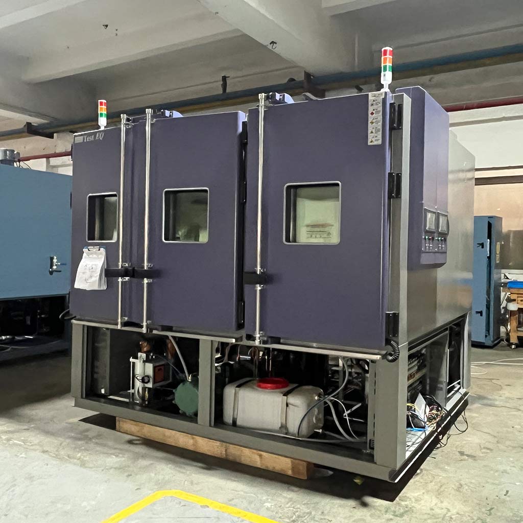
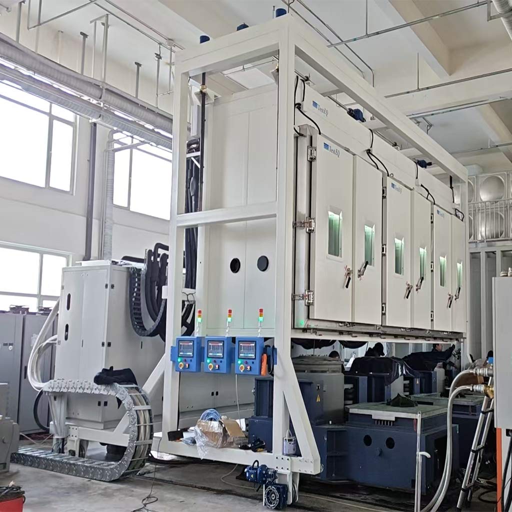
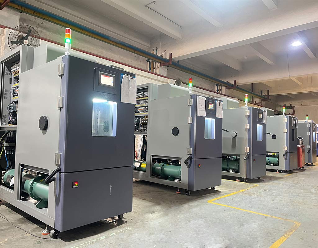
Thermal shock test, also known as high and low temperature shock test or temperature shock test, is to expose the test sample to a continuous alternating environment of high temperature and low temperature so that it experiences a rapid change in temperature in a short time, and assess the product's ability to rapidly change the surrounding environment temperature. It is essential in identification test and routine test, and can also be used in environmental stress screening test.Understand the thermal reliability of your PCB
PCB may encounter different temperature conditions in actual use, and temperature changes may lead to problems with PCB material and structure. Thermal stress tests can simulate these temperature changes and assess the reliability and durability of the PCB under such conditions. Through this test, potential problems and failure mechanisms can be identified, so as to improve and optimize.
Structural reliability testing of circuit board components
1. Thermal shock reliability. When a board is exposed to very high temperatures, it heats up very quickly, which can cause the mechanical components or conductors on the board to fail under thermomechanical stress.
2. Heat cycle. Thermal shock may occur repeatedly. Although the board may not heat up high enough to fail immediately, damage can accumulate over time as the PBC temperature cycles repeatedly between the two extremes. Over time, conductors may become fatigued (for example, through microcracks, corrosion, or pitting), and elastic materials may become brittle.
PCB thermal shock test test standard
IEC 60068-2-14: This standard specifies the cold and thermal shock test methods for PCBS at different temperatures. In the test, the PCB needs to be cycled at high and low temperatures to simulate the environmental conditions that may be encountered in actual use. The standard specifies the requirements for test equipment, sample preparation, test procedures, and result evaluation.
MIL-STD-883: This standard is one of the PCB reliability test method standards developed by the U.S. military, which includes cold and thermal shock test methods. This standard specifies the procedures and requirements for cold and thermal shock tests of PCBS at different temperatures, and is suitable for reliability assessment of military electronic equipment.
GB/T 2423.22-2008: This standard is one of China's national environmental test standards, which specifies the cold and thermal shock test method for PCB at different temperatures. The standard is similar to IEC 60068-2-14, but the specific requirements and test conditions are different.
JEDEC 190A: This standard is a standard developed by the Joint Commission on Electronic Equipment Engineering (JEDEC) for cold and thermal shock tests of PCBS at different temperatures. The standard specifies the requirements for test equipment, sample preparation, test procedures, and result evaluation
Thermal shock testing follows a variety of standards, and thermally reliable products should be designed to withstand the requirements of these thermal tests. With the best design toolset, design teams can implement thermal management methods to help prevent failures due to thermal shock, and JOEO is a leader in environmental reliability testing, covering every stage from material selection to regulatory approval to failure analysis. If you are interested in PCB or PCBA test methods, you can contact our engineers online, we will answer your questions immediately!