Why Thermal Cycling Causes Solder Joint Failures
Thermal cycling repeatedly exposes assemblies to alternating high and low temperatures. Every material expands and contracts at different rates.
When the coefficient of thermal expansion (CTE) of:
PCB substrates
Solder alloys
Ceramic packages
Silicon chips
Metal leads
does not match, cyclic stress accumulates inside the solder connection.
Over thousands of cycles, this stress eventually produces:
Micro-cracks
Grain boundary separation
Intermetallic compound growth
Delamination
Complete electrical failure
This phenomenon is known as thermal fatigue.
Main Failure Mechanisms
1. CTE Mismatch
Different materials expand at different rates.
For example:
| Material | Typical CTE |
|---|---|
| Silicon | 2.6 ppm/°C |
| Ceramic package | 6 ppm/°C |
| FR-4 PCB | 14–17 ppm/°C |
| Lead-free solder | 22–25 ppm/°C |
These differences create shear stress at solder interfaces during every thermal cycle.
2. Fatigue Crack Propagation
Repeated stress causes microscopic cracks to initiate near:
Component corners
BGA solder balls
QFN package edges
Large power devices
Cracks slowly propagate until electrical continuity is lost.
Typical failure modes include:
Corner crack initiation
Bulk solder fatigue
Pad lift-off
Open circuits
3. Intermetallic Compound Growth
High temperatures accelerate diffusion between:
Tin
Copper
Nickel
This produces intermetallic layers that become thicker and more brittle over time.
Excessive IMC growth can reduce mechanical strength and increase the probability of fracture.
4. Void Formation
Voids inside solder joints create stress concentration points.
Large voids can lead to:
Reduced current-carrying capability
Hot spots
Accelerated fatigue failure
Industries Most Affected
Thermal cycling-induced solder failures are commonly found in:
Semiconductor Devices
IC packages
BGA components
Power modules
Automotive Electronics
According to AEC-Q100 requirements, ECUs and sensors must withstand severe temperature cycling conditions.
Typical applications include:
Battery management systems
ADAS modules
Inverters
Power electronics
Aerospace Electronics
Aircraft electronics experience extreme altitude and temperature variations, making solder fatigue a critical reliability concern.
Renewable Energy Systems
Power converters and ESS systems frequently undergo thermal loading cycles that can shorten solder joint life.
Common Thermal Cycling Standards
JEDEC JESD22-A104
Widely used for semiconductor reliability evaluation.
Typical conditions:
−40°C to +125°C
15-minute dwell
Hundreds to thousands of cycles
IEC 60068-2-14
International standard for temperature change testing.
Applications include:
Electronic assemblies
Automotive components
Industrial equipment
AEC-Q100
Qualification requirements for automotive integrated circuits.
Failure Analysis Methods
Engineers commonly employ:
Cross-Section Analysis
Used to examine:
Crack initiation
Grain structures
IMC thickness
X-Ray Inspection
Detects:
Hidden cracks
Voids
Solder ball defects
SEM and EDX Analysis
Provides detailed microstructural information and elemental composition.
Electrical Resistance Monitoring
Tracks intermittent failures throughout cycling.
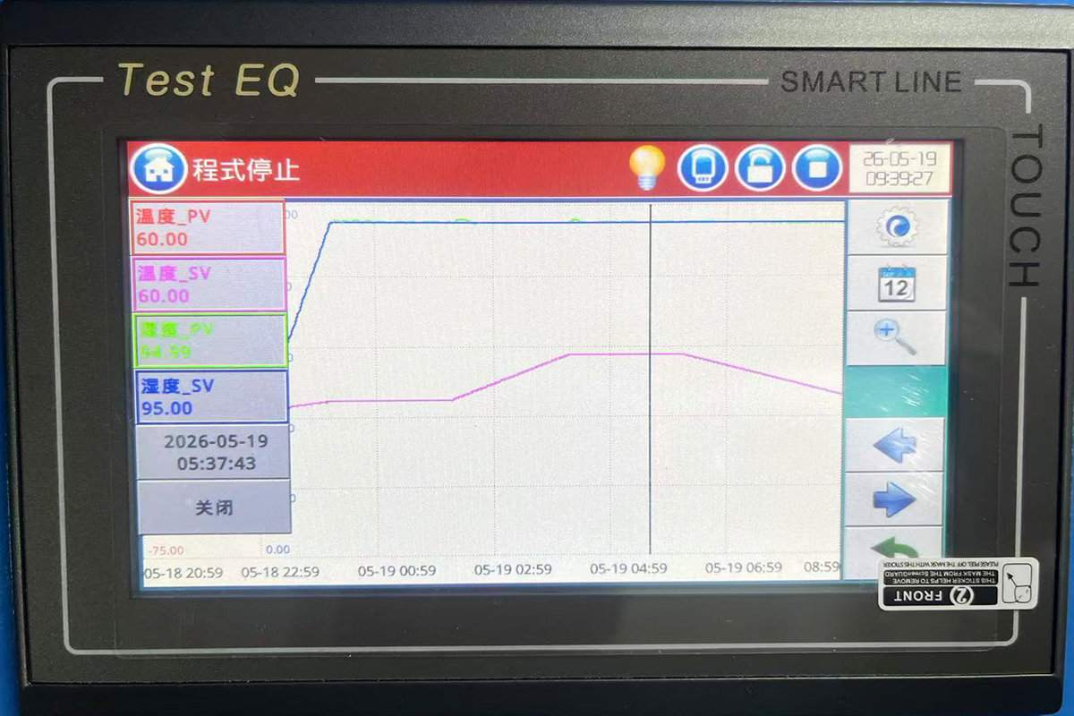
How Thermal Cycling Chambers Improve Reliability
Accurate temperature cycling is essential for reproducing real-world stress conditions.
Key chamber characteristics include:
Uniform temperature distribution
Fast ramp rates
Stable transition control
Long-duration reliability
Precise cycle repeatability
High-performance systems help engineers identify solder fatigue issues early in product development, reducing warranty costs and field failures.
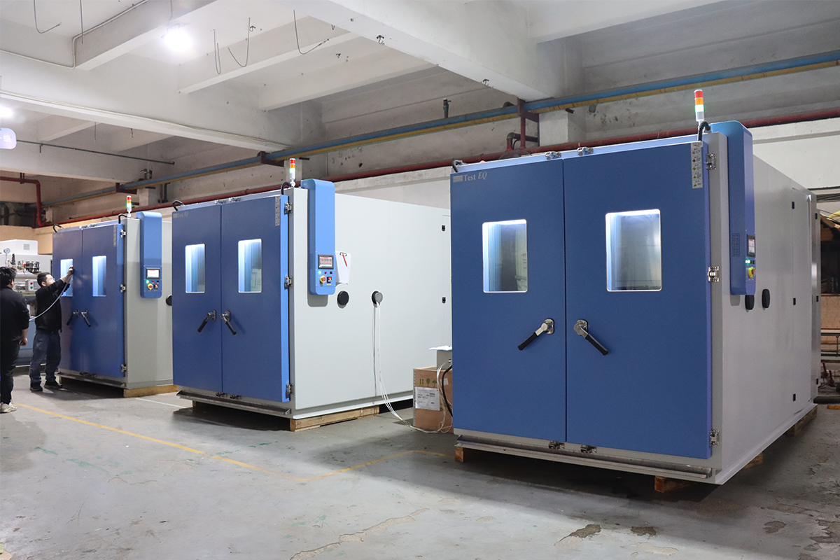
TestEQ Thermal Cycling Chambers for Reliability Testing
TestEQ provides advanced thermal cycling chambers designed for semiconductor, automotive and electronics reliability applications.
Key capabilities include:
Temperature range from -70°C to +180°C
Linear ramp rates up to 25°C/min
Excellent temperature uniformity
Compliance with JEDEC, IEC and MIL-STD requirements
Custom chamber sizes available
Suitable for PCB, BGA, IGBT and power module testing
These systems are widely used in:
Semiconductor laboratories
Automotive suppliers
Research institutes
Aerospace manufacturers
Electronic component reliability centers
Conclusion
Solder joint failures during thermal cycling testing are primarily caused by CTE mismatch, fatigue crack propagation, intermetallic growth and void formation. As electronic devices become smaller and more powerful, understanding these mechanisms becomes increasingly important.
By combining proper design, material selection and accurate thermal cycling equipment, engineers can significantly improve product reliability and reduce field failures.
For organizations performing JEDEC, IEC or automotive qualification testing, selecting a high-precision thermal cycling chamber is a critical step toward ensuring long-term electronic reliability.
FAQ
1.Why do solder joints crack during thermal cycling?
Repeated expansion and contraction create fatigue stress. Over many cycles, microscopic cracks develop and eventually cause electrical failure.
2.Which components are most susceptible to thermal fatigue?
BGA packages, power modules, large ICs and automotive electronics are especially vulnerable because of CTE mismatch and high operating temperatures.
3.Which standard is commonly used for solder joint reliability testing?
JEDEC JESD22-A104 is one of the most widely adopted standards for semiconductor thermal cycling reliability evaluation.
4.What temperature range is used in thermal cycling tests?
Common conditions include:
-40°C to +125°C
-55°C to +150°C
depending on the applicable industry standard.
Internal Linking Module
Related Products
Used for JEDEC and IEC temperature cycling reliability testing of semiconductor devices and electronic assemblies.
Designed for Environmental Stress Screening applications in automotive, aerospace and electronics industries.
Related Standards
Understand JEDEC JESD22-A104 requirements, temperature profiles and qualification procedures.
Learn how IEC 60068-2-14 defines thermal cycling and temperature change testing methods.
Related Resources
Compare the mechanisms, standards and applications of thermal cycling and thermal shock tests.
A practical guide for engineers and procurement teams selecting temperature cycling equipment.
CTA
Need a Thermal Cycling Chamber for Electronics Reliability Testing?
TestEQ provides custom thermal cycling chambers with temperatures from -70°C to +180°C and ramp rates up to 25°C/min, supporting JEDEC, IEC and MIL-STD qualification requirements.
"Contact TestEQ today to receive technical specifications," application recommendations and a customized quotation for your semiconductor or electronics testing project.